Project 5
Project 5A: Lightbulbs'R'Us and JPL
Continuing T.R.O.J.A.N forces collaboration with the Jet Propulsion Laboratory (JPL) Division of NASA, you and your team are working with a group of electrical engineers at Lightbulbs'R'Us. Given the problems that Lieutenant Pete “Maverick” Mitchell has been having with the warning lights, the Jet Propulsion Laboratory (JPL) Division of NASA has placed a large order for a new set of warning lights for their power delivery system. They have told you that a current of 2.5 A down the carrier wire should turn on the warning light. Unfortunately, due to JPL's time schedule, you do not have time to order LED bulbs and must construct the lightbulbs the old fashion way using a filament (very thin piece of wire, diameter = 0.1 mm) connected to the carrier wire (normal electrical wire, diameter = 1.63 mm). You happen to have the following metals in the warehouse, with known electron densities and electron mobilities.
JPL has asked for a product report on your design. They would like you to outline which metals you would want to use for carrier and filament, why you picked those metals, and the expected surface charge distribution for your set up. They would also like to know the total resistance of your design and the total voltage needed to power your bulb (so they know what kind of battery to provide).
Remember, a good solution includes explanations, diagrams, evaluations, and commentary in addition to your calculations. See the Project Write Up Rubric for more details.
Learning Goals:
- Describe what parts of the circuit provide power and which parts use power.
- Compare quantities like current, electric field, potential difference, and power for the thin and thick parts of the wire.
- Describe and draw the surface charge gradient for a thick and thin wire.
- Explain what is resistivity/conductivity and how it relates to resistance.
- Explain how current, voltage, and resistance are related and how you used these ideas in your solution.
Project 5B: Artemis's Last Hope
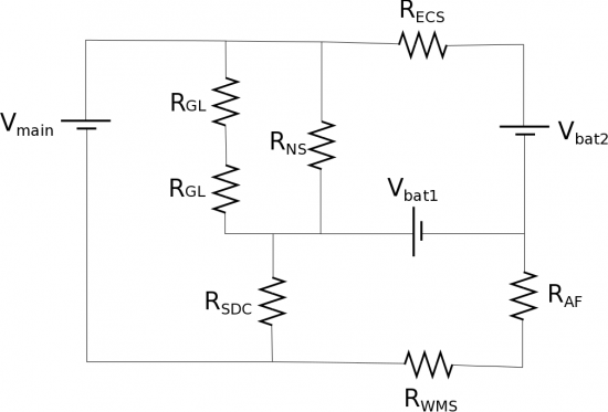
In part thanks to your brilliant work with the lightbulbs and JPL, the Artemis 13 Spacecraft was able to have a successful launch. While on the way to the moon, disaster strikes. Among other things, the air filtration system seems to be malfunctioning. Team leader Melissa Lewis decides Artemis 13 needs to go home ASAP. Just as she gives the order to rotate boosters in order to send the ship home, the crew feels the spacecraft rock violently and warning lights start going off everywhere. The command ship starts to lose all of its power (maybe it had something to do with not being able to get the special tape from the STICKYSTUFF corporation at Lakeview). After a quick investigation, it turns out that the circuit that controls all of the key systems is currently drawing too much current from the battery. You are in constant communication with Austin about the issues you are encountering and a bright but intense intern proposes a risky but possibly brilliant solution. They want to take two batteries from the mostly dead Command Ship and use them to help power the Artemis. In addition to the 230 V main battery, they say they need 140 V ($V_{bat1}$) from the Command Ship battery and only 5 V ($V_{bat2}$) from the backup battery to get them home. From the ship manual you find the following resistances for different components that need to be powered in order to get you all home:
- Gauge Lights: $R_{GL}=100\Omega$
- Navigation System: $R_{NS}=700\Omega$
- Steering/Direction Control: $R_{SDC}=950\Omega$
- Engine Cooling System: $R_{ECS}=500\Omega$
- Air Filter: $R_{AF}=300\Omega$
- Waste Management System: $R_{WMS}=425\Omega$
Will this circuit work without drawing any more than the 0.35 A from the main battery?
Learning Goals
- Use resistor combination rules to simplify a complex circuit (or parts of a complex circuit)
- Recognize when resistor combination rules do not apply
- Use loop rule and current rule to analyze a complex circuit

