This is an old revision of the document!
Induced Current Directionality Prediction
Now that we have taken some time to discuss how magnetic fields and induced current are able to interact, it is important to take some time a refine the skills needed to understand how to predict the direction of the induced current around solenoids, through a generalized approach. In these notes, we will discuss the approach needed to predict the direction of the induced current through various situations.
Right Hand Rule
As we have learned from previous notes, when discussing the right-hand rule for the induced current the focus is on the $d\vec{A}$. In your right hand, make a fist and place the thumb out. The thumb in this situation will be representing your $d\vec{A}$. The fist itself will be used to predict the induced current flow. Normally, these situations could be described as clockwise and counterclockwise when describing the direction of flow; however, as you may notice that by simply saying “Counter-clockwise” another observer would still be confused because this statement involves assumptions about the observation point. By utilizing this Right Hand Rule model, you will be able to grasp a better understanding of the direction of flow of the Induced Current as well as be able to articulate the direction to the best of your abilities also.
Approach
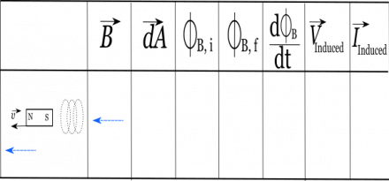
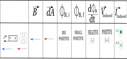
Let's take a moment and walk through how to solve the following situation utilizing the chart that we have laid out.
Step 1.) Direction of B-field
When given a magnetic bar, remember how the B-field flows. The B-field moves from the south pole to the north pole, then wraps around the magnetic bar as it flows back to the south. This B-field is also mirrored across the bar and will show a symmetrical flow to the B-field through a magnet.
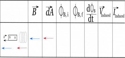
Step 2.) Choose the $d\vec{A}$
Remember that the $d\vec{A}$ is perpendicular to the cross section area of the solenoid. Meaning, that you can think of the $d\vec{A}$ as pointing “through” the solenoid. As far as what direction the $d\vec{A}$ should be, that is something you can choose between which end of the solenoid the $d\vec{A}$ will be pointed towards.
Step 3.) $\frac{d \Phi_B}{dt}$
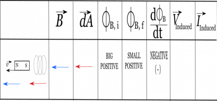
This portion of the approach is where the generalization of the situation begins. Meaning now we are going to talk about what the items: Big/small and Positive/Negative will mean. When we refer to Big and Small, we are using these terms to understand the relative impact that the situation has before and after with whatever object is moving. As we've seen before, the closer to the source the stronger the B-field. The farther away the observation point is, the smaller the B-field.
When referring to positive/negative we will be talking about directionality. If the $d\vec{A}$ that you choose is in the same direction as the B-field, then the flux will be deemed a positive flux. If $d\vec{A}$ and the B-field are pointing in the opposite direction (anti-parallel) then there will be negative flux.
Initial flux
Now that we have an understanding of the key terms we can start to walk through the table. The initial flux will be done BEFORE THE POSITION CHANGE of the object. Think about this as looking at the “Beginning of the Scenario”. From this observation, consider how much of an impact the B-field will have on the observation point. Are the objects closer before or after the position update? If CLOSER BEFORE, then we would deem this initial flux to be “large”. If CLOSER AFTER, then we would deem this initial flux to be “small”.
Final Flux
The final flux is calculated AFTER THE POSITION CHANGE of the object. Think about this as looking at the “End of the Scenario”. Compared to the initial position, if the objects are FARTHER, then we would deem this final flux to be “small”. If the objects are now CLOSER, then we would deem the final flux to be “large”.
Concluding
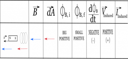
$\frac{d \Phi_B}{dt}$, remember, is the change in flux over a given time. Meaning that we need to calculate and understand the change of the flux as we start and end the scenario. Since these were generalizations given to find flux, the only thing we need for this approach is the sign of the change in flux. Meaning if I have a “Big Positive Initial Flux” (i.e. the B-Field and the $d\vec{A}$ are in the same direction and very close together at the beginning of the scenario) and then have a “Small Positive Final Flux” (i.e. the B-Field and the $d\vec{A}$ are in the same direction and relatively farther away at the end of the scenario). This change would result in a final $\frac{d \Phi_B}{dt}$ of a negative number. (Final – initial with the large value being in the latter.) Now that the direction of the $\frac{d \Phi_B}{dt}$ has been identified, we can flip the sign for the V-induced.
\begin{align*}
-\int \vec{E}_{nc} \bullet d\vec{l} &= \frac{d \Phi_B}{dt} &&&& (1) \\
-V_{ind} &= \frac{d \Phi_B}{dt} &&&& (2) \\
\end{align*}
This is now a built in check to see if the predicted $d\vec{A}$ was correct! If the V-induced value is positive, then your right hand will stay in the same direction that you started with. If the V-induced value is negative, then you must flip your hand to go in the opposite direction. Now that we have the properly identified $d\vec{A}$, we can utilize the Right Hand Rule Method to describe the direction of the I-induced.
Remember that the thumb represents the $d\vec{A}$ and the curl of your fingers describes the rotational direction that the current will flow. In our example, since the $d\vec{A}$ points in the positive -x-direction and the V-induced was positive, Meaning that if the induced current was occurring in the z-direction, we would label the answers as either “Into the page, then Out of the Page” or vice versa to describe the direction of flow. By utilizing this approach, students are able to have a formal methodology for approaching how to describe the directionality of the Induced Current.


