This is an old revision of the document!
Finding the Induced Current Direction
So far, we've been talking about the different pieces of Faraday's Law - namely how a changing magnetic flux will create an induced current. In this page of notes, we will outline the steps that we need to take to determine the direction of the induced current, which are based off of Faraday's Law itself:
$$V_{ind} = -\frac{d \Phi_B}{dt}$$
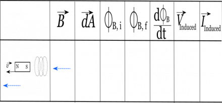
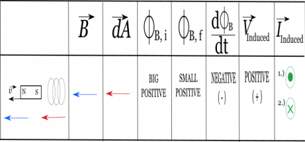
We will use the example of a bar magnet moving away from a wire coil to highlight these steps and to show how you can use a table to keep track of your work. While the specifics of the table will change depending on the context, the structure and steps will work no matter what problem you are solving. So to get started you should make a table like the one shown to the right with 8 columns. The first column will be for a picture/diagram of your situation, the second will be for the B-field direction, the third will be for the dA direction, the fourth will be for your initial magnetic flux, the fifth will be for the final magnetic flux, the sixth will be the change in magnetic flux, the seventh will be for your induced voltage, and the eighth will be for your induced current.
Right Hand Rule Steps
Step 1.) Draw a picture of your situation
Before anything, you should start with a picture of your situation. We'll draw this in the first column of the table. For our example, we'll have a bar magnet that is moving away from a set of coils. In the picture, we have marked the coils, the orientation of the magnet (which side is north/south), and which way the magnet is moving (marked with the velocity $\vec{v}$ arrow).
Step 2.) Draw the direction of the B-field through the relevant area
Next we need to determine the direction of the magnetic field through the relevant area. For this situation, the relevant area is going to be our coils, so we are particularly interested in the direction of the B-field through the coils. Remember for a bar magnet, the magnetic field should point out from the north side of the magnet, wrap around, and point into the south side of the magnet. Since our coil is next to the south side of the magnet, this means the magnetic field inside the coil will mostly be pointing to the left (in towards the south side of the magnet). So in the second column we will put an arrow to the left.
Step 3.) Choose the $d\vec{A}$
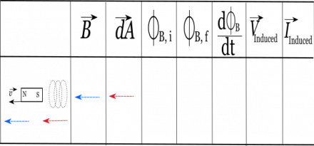
Remember that the $d\vec{A}$ is perpendicular to the cross section area of the coils. Meaning, that you can think of the $d\vec{A}$ as pointing “out of” the coil. For our set up, this means that $d\vec{A}$ could point either to the left or right (-x or +x direction). It doesn't matter which way you pick, as long as the $d\vec{A}$ is perpendicular to the area. For this example, we'll pick the $d\vec{A}$ to point to the left, so we draw an arrow in the third column that points to the left.
Step 4.) $\Phi_{B,i}$, $\Phi_{B,f}$ and $\frac{d\Phi_{B}}{dt}$
Now, we're ready to figure out what is happening to the initial flux, final flux, and therefore what is happening to the change in flux for the scenario. For this step, we don't need to do exact calculations. Instead, what we really care about is the relative magnitude of the flux (is it a big or small flux) and the sign of the flux (is it positive or negative?).
The magnitude of the flux will depend on the size of the B-field and area at that particular time. For example if your bar magnet is close to your loop, you'd expect a big flux since the magnetic field is stronger closer to the magnet. The sign of the flux will be determined by the dot product of $\vec{B}$ and $d\vec{A}$. Remember we can simplify the flux equation by saying: $$\Phi_B = \int \vec{B} \bullet d\vec{A} = B *dA *cos(\theta)$$ So if $\theta$ is between $0^\circ-90^\circ$, then we know the flux will be positive. If $\theta$ is between $90^\circ-180^\circ$, then the flux will be negative. So let's go through this for our example.
Initial flux
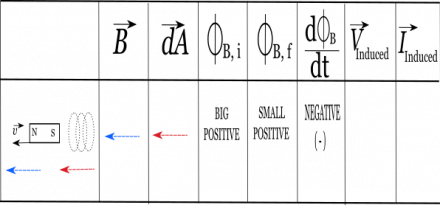
The initial flux is determined for the “beginning of the scenario.” For our situation, we start with the bar magnet initially close to the coil (and it will be moving away). This means that the initial magnetic flux should be relatively big through the coil since the magnetic field will be stronger closer to the magnet. The sign of the initial flux will be positive since both the B-field and the area vector point to the left ($\theta = 0^\circ$). So in the fourth column, we write that the initial flux will be “big and positive”.
Final Flux
The final flux is determined after some time has passed. Think about this as looking at the “End of the Scenario”. For our situation, this means the the bar magnet will have moved further away from the coil to the left. This means that magnetic field through the coil will still be pointing to the left (toward the south end of the magnet) but it will be smaller in magnitude since the magnet is further away. (Nothing has changed about our coil so the dA vector remains the same). This means that our final magnetic flux will be relatively small (compared to our initial flux), but the flux should still be positive since B and dA still point in the same direction. Thus in the fifth column, we write that the final flux is “small and positive.”
Change in Flux
Now we can determine the sign of the change in flux. Since we already have the initial and final flux values, this step is simple. We just use: $$\Delta \Phi_B = \Phi_{B,f} - \Phi_{B,i}$$
In our case, this means we'd be taking a small positive number minus a big positive number. This will result in a negative change in flux. (If it helps, you can assign numbers to help you think through this. For example, we could take $2-10 = -8$.) So we write down in the sixth column that the change in flux is negative.
Step 5: Determining $V_{ind}$
Concluding
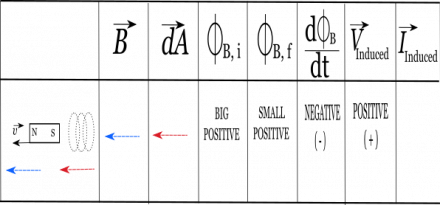
$\frac{d \Phi_B}{dt}$, remember, is the change in flux over a given time. Meaning that we need to calculate and understand the change of the flux as we start and end the scenario. Since these were generalizations given to find flux, the only thing we need for this approach is the sign of the change in flux. Meaning if I have a “Big Positive Initial Flux” (i.e. the B-Field and the $d\vec{A}$ are in the same direction and very close together at the beginning of the scenario) and then have a “Small Positive Final Flux” (i.e. the B-Field and the $d\vec{A}$ are in the same direction and relatively farther away at the end of the scenario). This change would result in a final $\frac{d \Phi_B}{dt}$ of a negative number. (Final – initial with the large value being in the latter.) Now that the direction of the $\frac{d \Phi_B}{dt}$ has been identified, we can flip the sign for the V-induced.
\begin{align*}
-\int \vec{E}_{nc} \bullet d\vec{l} &= \frac{d \Phi_B}{dt} &&&& (1) \\
-V_{ind} &= \frac{d \Phi_B}{dt} &&&& (2) \\
\end{align*}
This is now a built in check to see if the predicted $d\vec{A}$ was correct! If the V-induced value is positive, then your right hand will stay in the same direction that you started with. If the V-induced value is negative, then you must flip your hand to go in the opposite direction. Now that we have the properly identified $d\vec{A}$, we can utilize the Right Hand Rule Method to describe the direction of the I-induced.
Remember that the thumb represents the $d\vec{A}$ and the curl of your fingers describes the rotational direction that the current will flow. In our example, since the $d\vec{A}$ points in the positive x-direction and the V-induced was positive, Meaning that if the induced current was occurring in the z-direction, we would label the answers as either “Into the page, then Out of the Page” or vice versa to describe the direction of flow. By utilizing this approach, students are able to have a formal methodology for approaching how to describe the directionality of the Induced Current.


