Spring 2021 - Optional Final
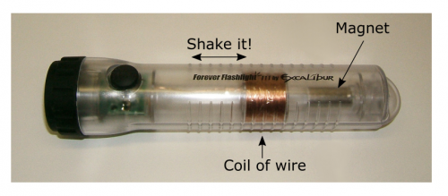
It's the end of the semester and the EM boar tigers have gone a little stir crazy. They’ve ruined Lakeview’s powergrid. Dr. Watersa is trying to finish up the last bit of her analysis for the team at the Hawkion facility, and has decide to build an induction flashlight (like the one shown below) to finish her work. When you shake the flashlight, the magnet moves through the center of the coil of wire, which induces a voltage. She's asked you to consult with her on the design.
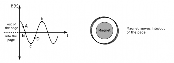
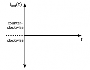
Dr. Watersa has happened to find a prototype of the flashlight design in storage made of a 100 turn coil with a radius of 2 cm. Thankfully the lab also has a variety magnets with maximum B-fields of: 100 μT, 200 μT, 300 μT, 400 μT. Dr. Watersa has decided the fastest that she'd be able to shake the flashlight consistently is with a frequency of somewhere between 2-4 Hz. She's started a rough graph of what she expects the B-field to be inside the coil, but has gotten distracted and needs your help to finish. Dr. Watersa has indicated specific points on the B-field graph that she is interested in and would like to know what direction the induced current would be at each point (or if it's zero at any points). She's also left space for a graph of the induced current and would like to know what is the maximum induced voltage that she can produce with the flashlight. Remember, a good solution is not just equations and numeric calculations, but will include commentary and discussion of those equations, reflections on what those predictions mean, and the limitations of your solution.
Learning Goals
- Use the right hand rule to determine the direction of the induced current
- Given a magnetic field graph, draw the corresponding induced current graph
- Calculate the $V_{ind}$ using the change in magnetic flux


